Board Details
Product Specifications and Software Summary
Jump To:
Orders received after 12/16/2025 will not be shipped until January 2026.
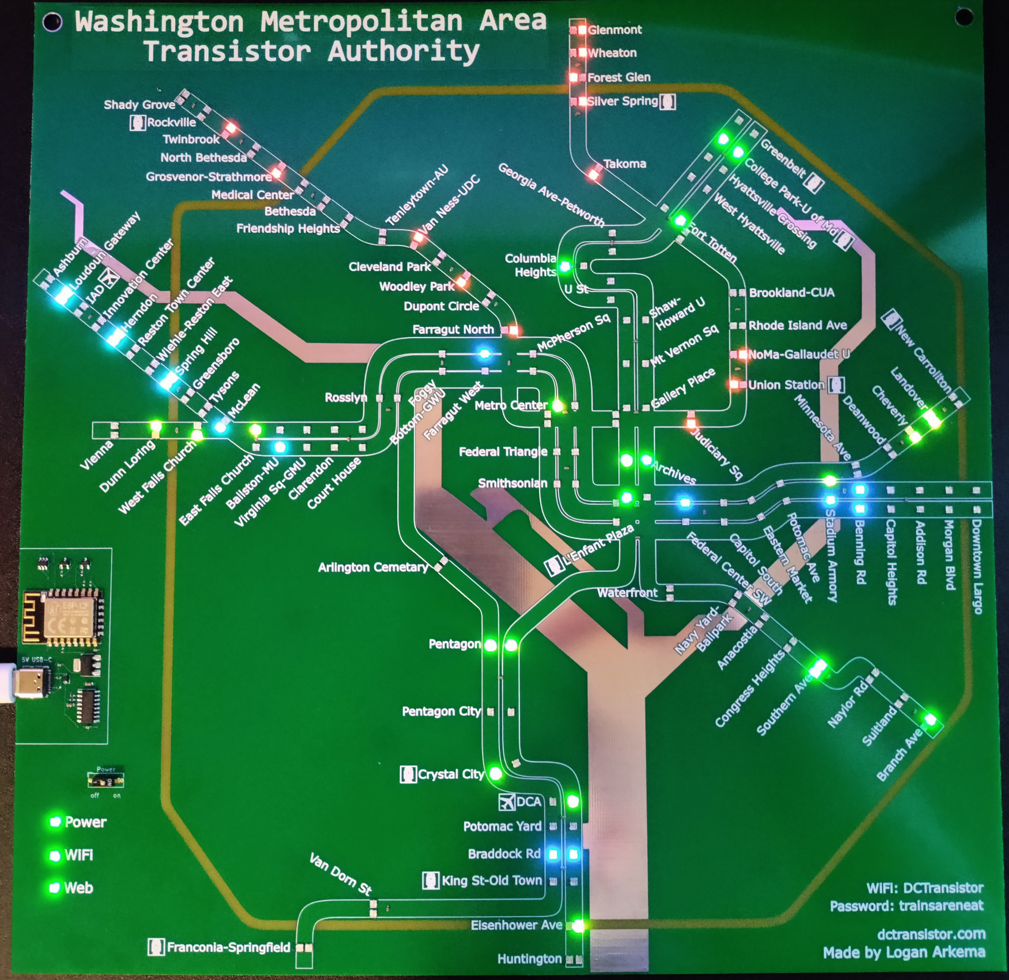
Standard Board
The “standard board” is the classic DCTransistor board with one LED representing each WMATA station. LED indicators will move in both directions along the single display for both directions of a WMATA line.
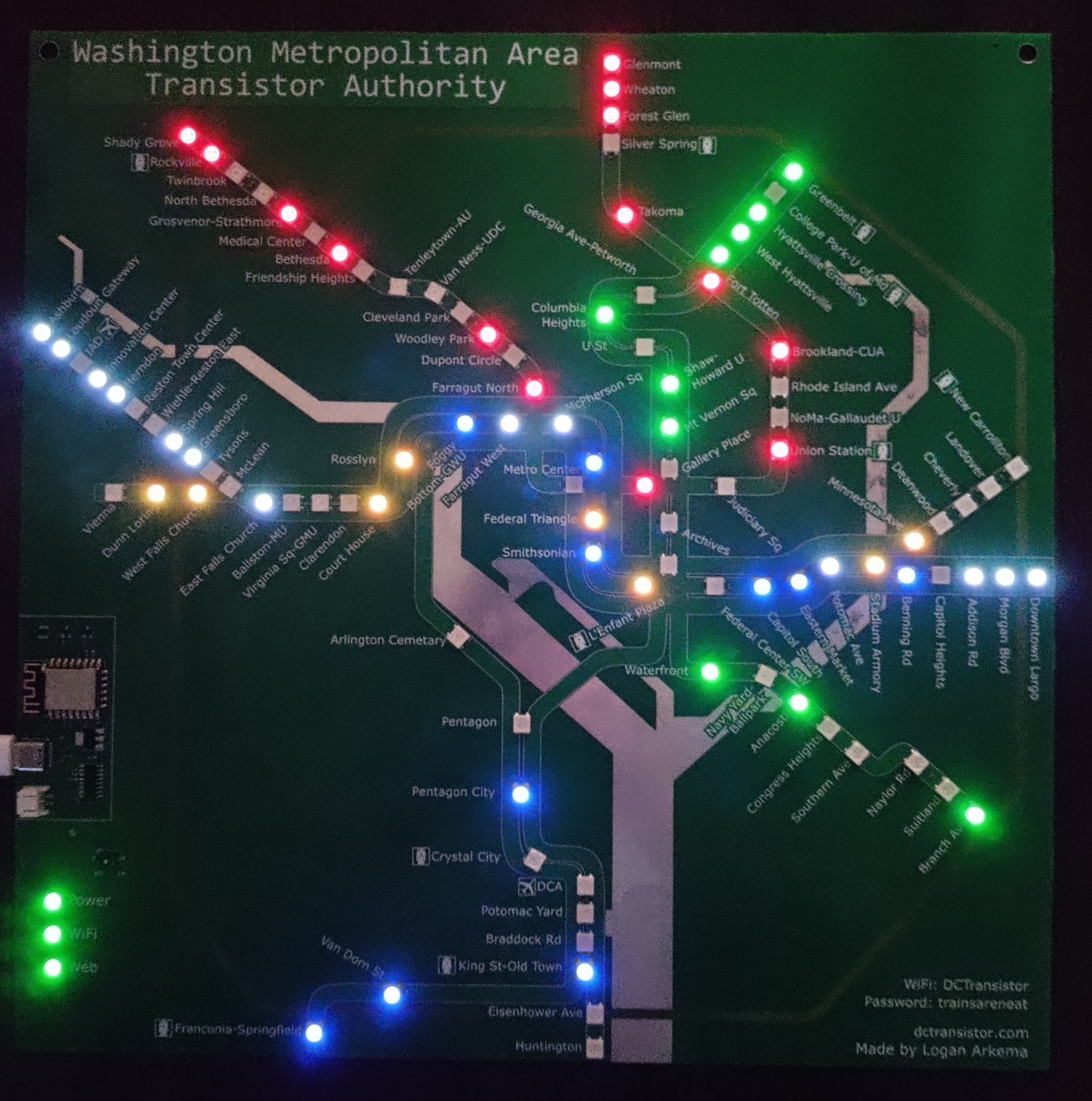
Bidirectional Board
The bidirectional board is here! With 207 individual LEDs, the bidirectional board has separate indicators for trains moving in both directions at each station. Indicators move on the “right” side of the track relative to the train’s direction. The bidirectional board takes the DCTransistor boards from a neat aesthetic item to a clearer visual representation of trains moving throughout the Metro system. Enjoy!
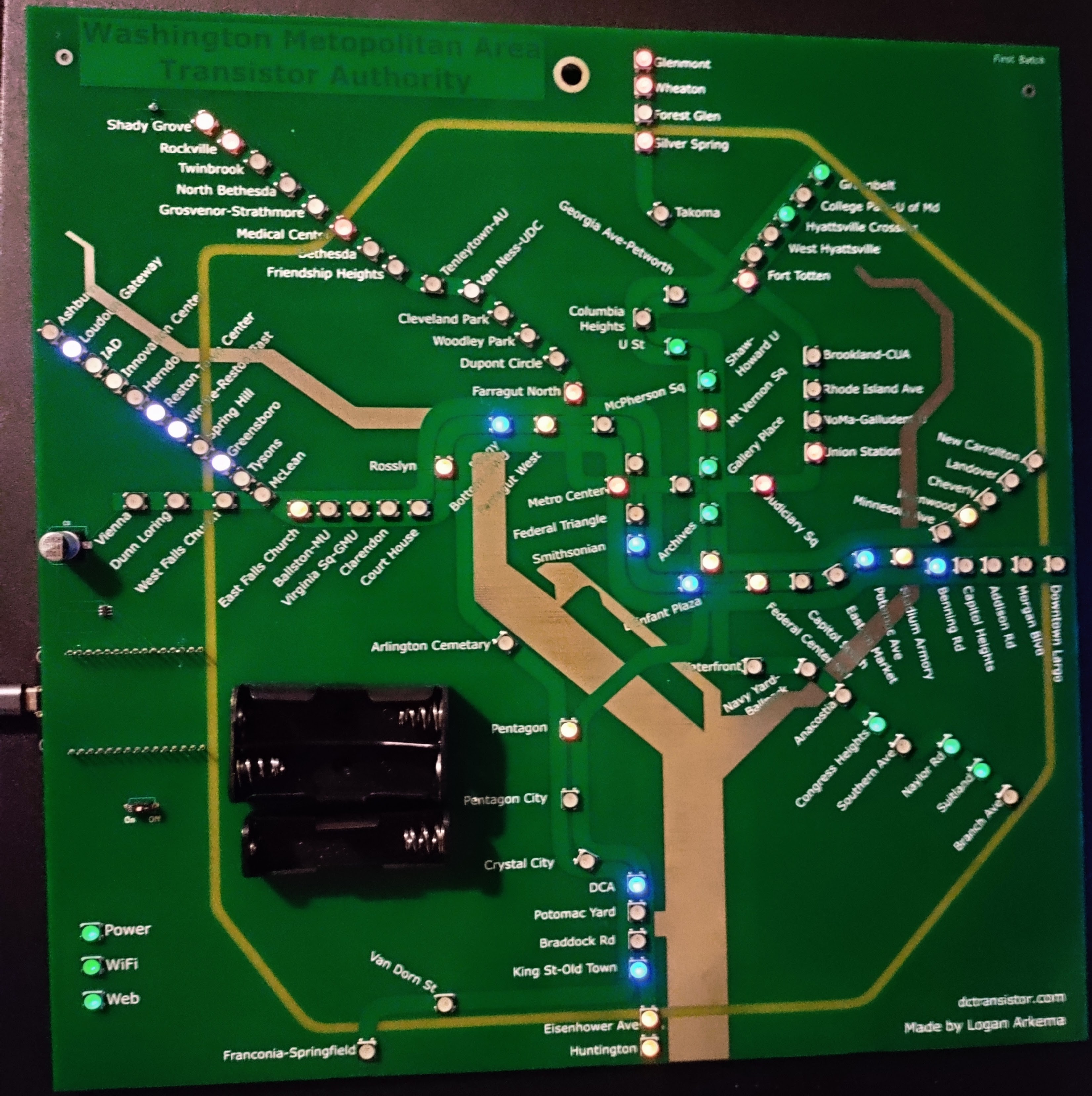
Dev Board
The “dev board” is one of the remaining batch of 10 prototype boards. The Dev board is perfectly functional and works the same as the Standard board, with a few notable differences to aesthetics and interface. The JST connector is replaced with an attached AA battery holder, the ESP32 chip running the board is attached through a separate development board - allowing custom GPIO connections to the chip and board, power is provided by a Micro-USB cable instead of USB-C, and the two side mounting holes are replaced by a single mounting hole in the center of the board. Some of the text on the board is also difficult to read. Also, the LEDs kind of suck and don’t some of the line colors. That said, there are only four (4!) left at the time of this writing and they’re cheap!
If you own or plan to purchase a dev board, be sure to read the information on the dev boards page.
How It Works
Boards work by getting real-time train positions WMATA makes available through it’s API, and turning on LEDs for the station a train is arriving at or most recently departed.
When the board turns on, all LEDs turn off except the power LED (some other LEDs may flash on with data from before the board turned off), then attempts to connect WiFi. At this point, the WiFi LED will turn yellow until it successfully connects (which may take a few seconds), and then it will turn green. The board then attempts to connect to the WMATA API, and the Web LED will turn yellow until it successfully receives the first batch of train positions.
WMATA provides a list of every train in service and the line and track segment they’re on. For each train, the board checks which stations the train is between, including if it’s arriving at a station (currently using two segments before a station as “arriving”); and records that the train’s line has a train at that station. After going through all active train positions, the board goes through all stations and sees if any line has a train “at” the station. If a line has a train “at” the station, the LED turns on to that line’s color, and turns off if no line has a train there. The board then updates all LEDs to show the new positions, and waits twenty seconds before getting new train positions from WMATA.
Important: Train positions are taken directly from WMATA, and are only as accurate as the location data WMATA provides. In particular, WMATA may report a train’s position “at” a station that is closed for repairs, or “at” the station before a series of closed stations long after a train has left. Further, a segment is not a uniform measurement, so while a train may move on the board because it is two circuits away from the station it may not be close enough for an “ARR” message to appear at a station. Finally, the board has LEDs for stations that are not yet open as of April 2023 (i.e. Potomac Yard), and therefore do not turn on. I will try to release software updates as soon as the stations open, but make no guarantees on timeliness. While boards have an auto-update feature, the software is provided as-is and comes with no guarantees or warrantees.