Dev Board Information
Details about the dev board and how to use it
Power Your Board
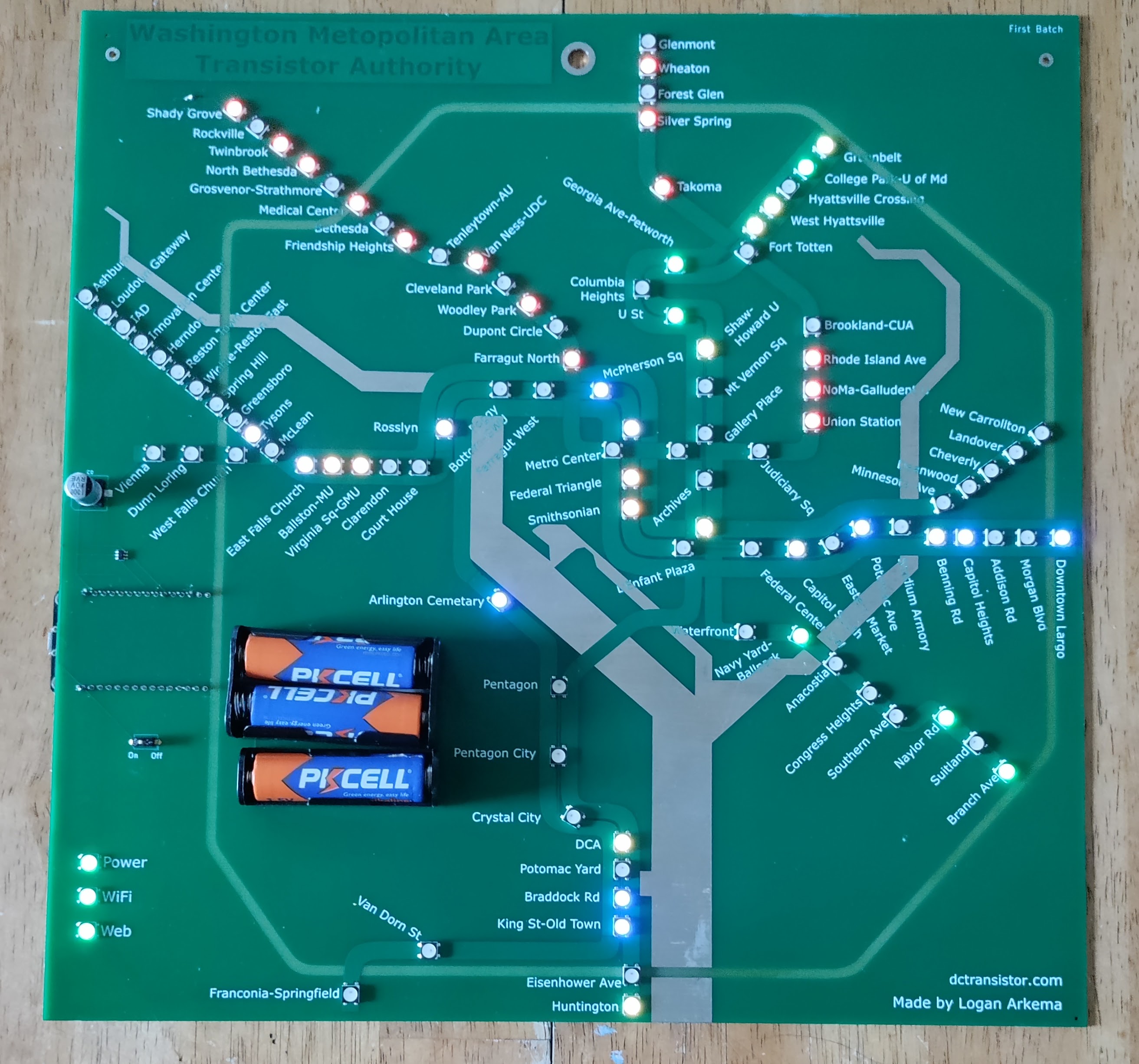
Boards can either be powered through a Micro-USB cable OR 3 AA batteries. While you must use a USB cable connected to a computer to load the software, you can then use a cable from a phone charger or other direct power supply as long as it supplies power at (or near) 5 Volts (more than 5V may permanently damage the chip or LEDs on the board).
You can also power the board using 3 AA batteries, which are controlled with an “On/Off” switch. If using batteries, make sure the power switch is set to “Off” while inserting the batteries. For additional protection, begin inserting batteries from the bottom up, as the bottom battery grounds the board while the top battery connects to power. Providing power via the top battery without a connection to ground may also cause permanent damage to the board.
Finally, DO NOT CONNECT THE BOARD TO USB AND BATTERY POWER AT THE SAME TIME. This will provide far more power than the chip or LEDs are able to handle, and again may cause permanent damage. While it is possible to leave batteries in the board with the switch turned off while connected to a USB power supply, I recommend taking at least the top battery out to ensure extra voltage isn’t supplied to the board.
Differences
There were multiple adjustments from the prototype board to the current production board. Specifically, I:
- Fixed station names that get cutoff by the river or beltway designs
- Made small, miscellaneous adjustments to LED and station name positions
- Added silk screen (white text) to the board title to make it stand out more
- Increased the size of the top mounting holes so the board can more easily be screwed onto a surface or mounted on a hook
- Replaced the development chip soldered onto the back of the board with individual components integrated onto the front.
- Replaced the Micro-USB / USB-B connector with a USB-C connector
- Powered the board with an optional battery connector instead of the built-in battery holder.
- Connected the On/Off switch to USB and battery power supplies (currently only works with battery power)
- Added smaller capacitors throughout the board instead of the one large one currently on the left-middle
- Made other small technical fixes to the board design
Customize Your Board
To customize, or even update (for old software versions), your board:
- Download Arduino IDE
- Download the dctransistor code
- Download required support software and libraries
- Add ESP8266 Board to Arduino
- Add ArduinoJson and Adafruit_NeoPixel libraries to Arduino
- (Optional) Register for a WMATA API Key (if you want to monitor how your board uses WMATA data)
- Modify the
config.hfile with your changes and (optional) WMATA API key and - Plug in the board to your computer and upload the dctransistor sketch
- Make sure you have selected the ESP8266 board, a 9600 baud rate, and the correct COM port for the board in Arduino’s
Toolsmenu.
- Make sure you have selected the ESP8266 board, a 9600 baud rate, and the correct COM port for the board in Arduino’s
Once the tools have been installed, you can begin making tweaks to the
The main code (.ino) file sets a number of configuration values, most of which will break the board’s functionality if they are changed. However, the configuration values for each line (starting around line 60) have their LED color
defined with a <line_code>_HEX_COLOR 32-bit WRGB hex value, which you can change to whatever colors you want. In addition, all_lines array, defined right before the setup() function defines the order for what color a station LED will turn if two trains from different lines are “at” the same station (going opposite directions, one right behind another, etc.). You can change the order if you’re partial to one line over another.